MENU
Using dc power systems1 in parallel connection to a bus bar array is one of the most common design architectures2 deployed for redundancy. A very common product conversation starts with the question along these lines; “Need to know if I can run two systems to different breakers on a panelboard as a redundant scheme?”
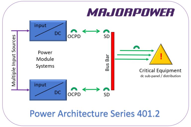
Nutshell Answer: “YES, you can operate two systems connected to a common dc bus bar (panelboard) through individual circuit breakers, as questioned for the redundant power architecture.”
The MTS-Com controller3 for each system will monitor, adjust, and report the status of the power module4 in that controller’s system, exclusively. A power designer can set two voltages since each system will contain an independent controller and module.
Laws of dc will prevail and both systems (via the bus bar) will share the load unless the designer plans to separate system voltages to steer current from the higher-voltage system. We suggest programming systems with a 2% output voltage separation and observe Ohm’s Law magic.
Using the redundant systems approach without double landing on a single system chassis terminal block is the best practice for a dual-system power architecture.
Each connection should contain a switching device (SD), at the bus bar, for each power system. The method is required to separate each system from a panelboard (dc bus bar) as cold-maintenance5 may be required in the future. Utilizing a basic switching device reduces the need for trip-coordination analysis (provided the switch is rated appropriately) of other over-current protection devices (OCPD) inline on the circuit. The Majortel power system over-current protection device is an integrated part of the system output in the connection toward the bus bar. The trip-current rating is marked on the front of each system containing OCPDs.
The caution note follows that if a Power Module System is in a power off mode (de-energized), the dc wire connections could be live(energized) from the alternate dc system back feeding from a bus bar if the design is not built incorporating a disconnect method; either SD or OCPD.
PA Series 401.2
Focus on the dc bus bar configuration will only be as resilient and redundant as the available input source to any power system. Take a moment to plan input source attachments to multiple points for elimination of any single-point-failure in the architecture. <save a copy>
1 – System: The power shelf equipped with integrated controller and power modules.
2 – Parallel Architectures in this article are combining ONLY dc circuits.
3 – Controller: The MTS-Com module inserted into the power shelf containing operational software.
4 – Power Module: DC output power modules can either operate ac-to-dc (rectifier) or dc-to-dc (converter).
5 – Work performed on de-energized circuits and equipment.
About the Series
Common Applications
Insights into the most common power architectures using our product line is the focus of the 202x Insights series. Review this Insider’s Link to applications and creative power architectures deploying power conversion products in the Majortel and Majorsine families. Our Majorpower Applications department answers common questions and shares the collective experience.


