Majortel System Controller
Integrated Monitor & Alarm Control Module: MTS-Com
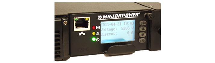
Each Majortel DC power system is equipped with a controller module labeled MTS-Com. LCD display, LED indicators and push button keys, on the front panel of the MTS-Com monitor, are standard design elements of this module. The user signal terminal connector is located on the rear of the system and integrates into this module through the internal backplane. Examples of telemetry signaling include temperature, digital input and alarm output; dry contact relay connections. Internally, CAN communication ports facilitate the MTS-Com supervisory signals to and from system elements.
Remote monitoring is capable through the Ethernet port supporting SNMP and Web-TCP/IP protocol. Utilize the front panel buttons to set a system IP Address, Net Mask and Gateway for the specific user network. Start any browser and ping the assigned IP address for access to the main monitor webpage. The most common status/functions can be monitored, configured and changed remotely.
Where is this Used?
Benefits
- Integrated TCP/IP port; (10/100)
- On-Board Web Engine
- SNMP v2 Integration
- Private Network Configuration
- Programming Control Buttons
- LCD screen for Status & Alarm
- Overview LED Summary Indications
- Two Level Alarm Summary
- Email Notification
- Audible Alert
- Dry-Contact Relays
- Hot-swap and Fault-tolerant Module
- Two Levels of Access Security
|
|
Feature Summary
- Date and Time
- Voltage Output
- High Voltage Rectifier Shutdown
- System DC Voltage Triggers
- Current Output
- Summary System Monitor
- Battery Current Draw Monitor
- Alarm Summary Indicator
- Alarm Relay Mapping
- Alarm Relay Position – Normal Status
- Alarm Tone On/Off
- Alarm Active Status
- Alarm History File Clearing
- Charge Rate and Current Limit
- Force Equalize Charge
- Define interval in days
- Battery Size
- Low Voltage Battery Disconnect trigger
- Ambient Temperature Monitoring
- Temperature Compensation
- Define center temperature
- Define compensation coefficient
- User and Supervisor Passwords
- Firmware Revision
- Network Controls
- IP Address
- Network Mask
- Gateway
|
Full Content Explanations
Date and Time
The date/time should be programmed and stored in the system. The d/t will be used for alarm file time stamping. This status parameter is shown on the main screen of the MTS-Com controller.
Voltage Output
Float: A float voltage is the normal charge voltage for the application. Users can program this voltage using the front panel or web page application.
Equalize: The equalize voltage can be used for applications requiring a temporary elevated charge voltage. Users should consult the battery manufacturer for specific details related to equalize charge routines.
High Voltage Rectifier Shutdown
High voltage shutdown setting will trigger self-protection mode in a system. This programmable setting is used by a controller when monitoring the overall bus voltage. If high voltage is detected, the voltage from each rectifier will cease output operation to protect the load and system.
System DC Voltage Triggers
DC High: High voltage alarms will be triggered when the bus sensor moves above the desired set point.
DC Low: Low voltage alarms will be triggered when the bus sensor moves below the desired set point.
The alarms automatically clear when the voltage returns to normal.
Current Output
Summary System Monitor
Summary current indications are displayed on the system monitor. This current measurement is a combination of the output current, as reported by each rectifier to the central controller.
Battery Current Draw Monitor
Battery current is measured using a shunt that is in series with the batteries circuit. Battery current draw indication is used to predict run-time, current limit or recharge duration.
Alarm Summary Indicator
Major Type – corresponds to red LED on the front panel.
Minor Type– corresponds to yellow LED on the front panel.
Alarm Relay Mapping
Operators may use this option to establish mapping of specific alarms onto one of two dry-contact relays. In addition to mapping an alarm to a relay, the alarm level can be classified as either major, minor or ignore.
Alarm Relay Position – Normal Status
All Majortel Systems ship with relay positioning set to Normal-Close relay operation. Relay status position can be programmed using the front panel buttons on the MTS-Com. Dry contacts are designed to make or break the alarm circuit supplied by the operator installation.
Alarm Tone On/Off
Operator programmable option for the audible alarm tone. Default setting is OFF. Active alarm audible tones will time out after 75 seconds. The active alarm will remain on the active status page.
Alarm Active Status
Operators can view the active alarms for the system being monitored.
Alarm History File Clearing
The alarm history table will store 200 events. Each event receives a time stamp. Round file operation will overwrite the oldest table entry.
Charge Rate and Current Limit
See page reference for detailed description of charging parameters.
Force Equalize Charge
Define interval in days
Waiting period, in days, between pre-programmed charge routines.
Define time limit
The time in minutes before an equalize charge will cease and the system returns to float voltage operation.
Battery Size
Operator programmed battery size based on the installation. Numerical value in AmpHours. This value is important to the calculation of the current limit function during recharge.
Low Voltage Battery Disconnect trigger
The voltage set in this parameter is used by the controller to open the internal contactor in the battery circuit. The contact will close the circuit after a system bus voltage is normal. Typical disconnect voltage is calculated by using 1.75 volts per cell for the battery installation. By example, in a telecom network configuration, 24 cells X 1.75 volt equals a 42v trigger setting to open.
Ambient Temperature Monitoring
A temperature probe is shipped with each Majortel dc power system. Once the probe is connected, the system will register the ambient temperature measured in the location and display this information on the screen. The probe is equipped with a 3 meter cable which allows positioning near the battery. The registered temperature is also used by the controller for the temperature compensation calculations and voltage adjustment.
Temperature Compensation Operation
Define center temperature
Default center temperature setting is 25° C.
Define compensation coefficient
User defined parameter used in the calculation to modify charge voltage in relationship to the change of temperature as measured. This setting will effect system overall voltage.
User and Supervisor Passwords
Two password levels in the Majortel controller. The user level password is used for basic monitoring. The supervisor level password includes system settings and password control options.
Firmware Revision Monitor
This is a read only field for viewing firmware installed in the controller being monitored.
Network Controls
IP Address
Network Mask
Gateway