MENU
What is the “temp-comp” feature all about in a dc power system?
The 2V cells in the big battery stacks require 3mV/cell/t° by manufacturing standards.
Therefore, 0.003V per cell change (up/down) by the charging system in response to each degree variation. The calculated voltage factor is programmed into a rectifier/charging system. The factor must be adjusted to match the battery type, size and nominal voltage operation. The most common factors are listed below as examples.
By Formula
mV * number of cells = change in voltage for a typical system type (nominal volt)
0.003 x 60 = 0.180 (120V)
0.003 x 24 = 0.072 (48V)
0.003 x 12 = 0.036 (24V)
Temperature Up – Voltage Down
Optimum battery system operation is in an environmental controlled area of 25 degree C. If the temperature shifts, the best practice proposes the charger change the voltage to counter any temperature rise in the battery. Voltage change is the inverse relationship as compared to the temperature variation. As temperatures get warmer, a voltage will decrease. Lower temperature changes will result in voltage moving higher.
The voltage change should end at 2.175V per cell, using default settings. This is just about 50°C. The change is consistent with the IEEE or NEMA Standards for low voltage per cell charging. We provide menu flexibility to the user allowing a charge voltage drop to 2.145V/C or 60°C as an adjustable cut-off point. Our default High-Temp setting is 50°C to protect batteries in most applications. Always refer to the battery manufacturer’s documentation for charge voltage requirements. “Read More about Charging in the Heat”
Install the Temp Compensation Probe
A) Use a small gauge flat-blade screwdriver in the top portal to leverage the spring open, once open insert the stripped alarm wire in the lower access port on the spring-clamp block.
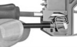
Probe Connector
B) Note that the probe’s SOLID-COLOR wire should be placed in the POSITIVE marked position and the color-with-stripe wire will be placed in the negative marked position. The insulated probe should be secured on or near the battery post for best results and accurate temperature compensation.
Adjusting the MTS-Com Settings:
1) Enter the system parameters menu from the front panel.
2) Navigate to the battery setting sub-menu and scroll down to make changes on:
3) Center Temperature; “CenterTemp” (degrees)
4) Temperature Compensation Coefficient; “TempCompCoeff”. (millivolts)
5) Press Enter and then Escape to the top level menu for saving the adjustments.
Contact us if you have additional questions or need assistance with these features.


