MENU
Insights into the most common power architectures using our products. Review this Insider’s Link to Common Applications. Our Majorpower Applications department answers common questions and shares the collective experience here.
Connector Reference
Jump to Converters
Jump to Inverters
Jump to Rectifiers
Jump to Hybrids
202.1: Single System implementation is the most basic conversion from one voltage to another voltage with single point to point connections; IN to OUT. The Majortel (MTD Converter) provides the additional second output breaker as the standard frame build, based on multiple client application requiring two output circuit connections to equipment apparatus.
Figure 1: OLE-MTD48/50-130-1U System
202.2: Building on the diversified input structure concept, picture a power system, labeled ONE, with protective devices connected to the A input of load-X and load-Y utilizing individual circuits, then deploy power system, labeled TWO, with devices connected to the B input of load-X and load-Y. The four connections facilitate isolated and multiple paths for dc power support to the specialized apparatus. The A/B dc support path has now been established one diversified level into two power supply systems. The loss of a single power system should not dramatically effect operation.
While this illustration derives a primary source from utility energy storage system. The common equipment deployment is a 130V dc input converter to a 48V dc output. The fault-tolerant overlay is utilizing the existing 130V storage system already installed and being maintained by the utility provider.
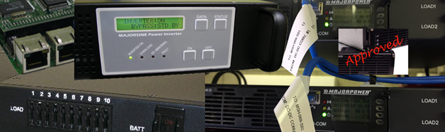
101.1: Inverter power architectures are the choice for high availability AC power support from a DC source. The integrated MAINS bypass circuit provides that alternative resource to keep critical equipment apparatus operational.
MAJORSINE inverters feature IGBT (Insulated Gate Bipolar Transistor) technology, minimizing weight and dimension, while enhancing output short circuit reliability and overload capacity.
Output voltage is provided to loads in one of two ways:
1) From AC input bypass mode: (Off-Line Mode)
2) From DC to AC inverter mode: (On-Line Mode)
Either mode is front panel programmable; the selected operational mode will determine the “default” output if both sources are available. Configurations are saved even though full power off.
In the first option, Off-Line mode, AC output power will be supplied through the AC bypass mode in its “normal” operation. Upon AC input failure, output power will be diverted through the DC to AC inverter mode. Once AC mains are restored, the unit will revert from inverter mode to bypass mode.
In the second option, On-Line mode, AC output power will be provided directly by the inverter from the VDC source. Should the DC source or inverter fail, the system will transfer its output power through the bypass mode. Once the DC power source is restored, the system will revert to “inverter” mode.
Transfer time from inverter to bypass, or bypass to inverter is <4 mSec. The Off-line/On-line mode is changed from one to the other by pressing the ON button for 3 seconds when normal output is available. The operational mode cannot be changed during an abnormal or faulted condition.
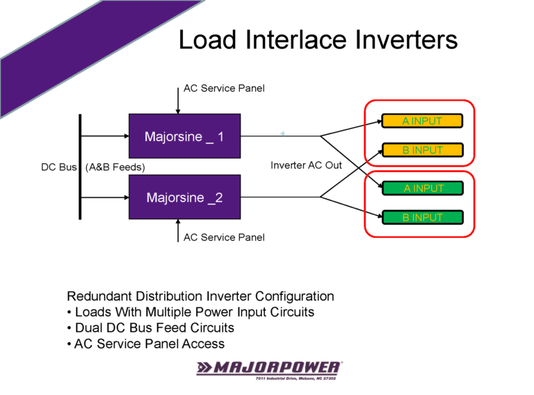
101.2: Inverters can also be configured for interlace power support. Often a client has asked to ADD more capacity by combining the load outputs of the inverter. This is a BAD scenario and ends up damaging both inverters. “Don’t do it” is typically followed by the suggestion of dividing the loads across multiple inverters. The divided load strategy increases the diversity and resilience of the application by spreading the capacity for fault-tolerant configurations.
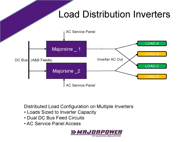
101.3: The Distributed Architecture involves an organized distribution of loads attached to multiple inverters. It is recommended to place half the network (critical) load on one unit and the remaining half on a second unit. A visual along the lines of splitting parent and child processes across two inverters.
Group network load elements together that help the application survive.
Each critical load apparatus is isolated and operates on a single ACV input termination; Load A-D. The separate inverter outputs must never be connected to the same point.
Loads are sized to remain within the capacity of each inverter. Individual DC bus circuits are connected to inverters. Individual AC main supply circuits are connected to inverters.
Power AC to DC Systems
401.1: For simple power architectures, configure a power shelf and two or more circuit protection devices, for example fuses or circuit breakers. A single power shelf system can support many A/B loads when the current requirements are low and the adequate protection devices are installed. Alternating-current (ac) diversity is managed through individual power module cord connections. Consideration given to each source of the “utility mains” connection can increase the fault-tolerant design. For example, one ac source might be directly connected to house mains and the second source might be connected to an uninterruptible ac power appliance. Power modules installed in a common system shelf share the direct-current (dc) bus connection. The aggregated dc power is then distributed to the source side of protection circuit devices. A specialized apparatus is connected to the load side of each protection device. When the overall load power requirement, called “N”, is within the rating of one power module, a system will be considered an N+1 design. As a concept, N refers to the load support using one power module and the second power module is effectively in a hot-standby ready status. Reality being that power modules share the bus, therefore, both support a portion of the load requirement until such time a fault condition (IE: one power module off) will cause a single power module to supply power to a full load. Individual circuits, called A/B, from a distribution panel isolate the connection from the power system to either of the apparatus loads. Multiple connections work to eliminate single element failures, whether in a material defect or unintentional cable pull action by personnel. It is possible to include additional load apparatus, J and K, into the power architectures after current-draw analysis and sizing the power capacity of the system to meet actual demand. A load-based configuration will analyze the current draw of each load apparatus connected to a protection circuit. Apparatus can be added to the power system until the aggregate current is slightly less than the capacity of a single power module when the N+1 configuration is implemented. Apparatus can be added to the power system until the aggregate current is near the total capacity of the power system, provided this is the design engineer’s intended operation. Risk analysis will vary between applications.
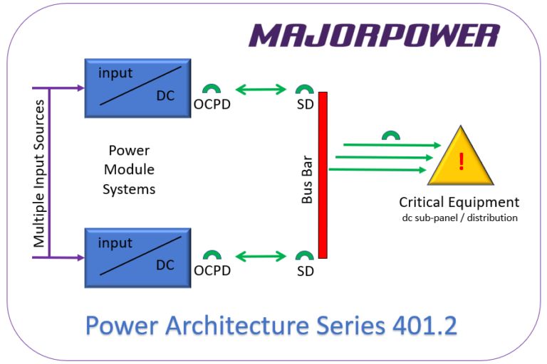
401.2: TWO Systems Landed on ONE Bus Bar Array
Using dc power systems in parallel connection to a bus bar array is one of the most common design architectures deployed for redundancy. A very common product conversation starts with the question along these lines; “Need to know if I can run two systems to different breakers on a panelboard as a redundant scheme?”
Nutshell Answer: “YES, you can operate two systems connected to a common dc bus bar (panelboard) through individual circuit breakers, as questioned for the redundant power architecture.”
The MTS-Com controller for each system will monitor, adjust, and report the status of the power module in that controller’s system, exclusively. A power designer can set two voltages since each system will contain an independent controller and module. Laws of dc will prevail and both systems (via the bus bar) will share the load unless the designer plans to separate system voltages to steer current from the higher-voltage system. We suggest programming systems with a 2% output voltage separation and observe Ohm’s Law magic.
Using the redundant systems approach without double landing on a single system chassis terminal block is the best practice for a dual-system power architecture.
PA Series 401.2
Applying the Concept
Each connection should contain a switching device (SD), at the bus bar, for each power system. The method is required to separate each system from a panelboard (dc bus bar) as cold-maintenance may be required in the future. Utilizing a basic switching device reduces the need for trip-coordination analysis (provided the switch is rated appropriately) of other over-current protection devices (OCPD) inline on the circuit. The Majortel power system over-current protection device is an integrated part of the system output design in the connection toward the bus bar. The trip-current rating is marked on the front of each system containing OCPDs.
The caution note follows that if a Power Module System is in a power off mode(de-energized), the dc wire connections could be live(energized) from the alternate dc system back feeding from a bus bar if the design is not built incorporating a disconnect method; either SD or OCPD.
Engineering Consideration: Focus on the dc bus bar configuration will only be as resilient and redundant as the available input source to any power system. Take a moment to plan input source attachments to multiple points for elimination of any single-point-failure in the architecture.
401.3: Load or Battery using the MTS130/20AT-1U power system but not both.
Power Architecture Series Cynosure:
In a load mode, the two-pole circuit breaker is attached to the equipment apparatus. The sole purpose of this system is power supply production at a single stable output voltage. A wide range of installations operate in this capacity whether downstream from a UPS or as a temporary dc power source in a critical maintenance window procedure. The user selectable mode will mask the battery parameters of the man-to-machine interface to assure top level voltage settings are focused on the single output voltage operation.
In a battery mode, the two-pole circuit breaker is attached to the common bus for the installation, being upstream of the battery and equipment apparatus. Alternatively, the two-pole circuit breaker is attached to the battery posts, for the installation, and both are upstream of the equipment apparatus. The purpose of this configuration is twofold as a power supply to load apparatus and battery charge source producing a temperature compensation managed output. The temperature probe must be installed to collect valid data that is referenced to alter the voltage. This system is designed for full output capabilities and ultra-smooth ripple with or without battery attachment. A term often attached to charger/dc power systems of this design might include “battery-eliminator” mode to imply low-ripple characteristics without the connection of a battery to tame rectification circuits.
401.4: Power supply ONLY using the MTS48/50AT-1U connection to existing bus work installation. Keys: • When existing dc plant load is unchanged, but a new rectifier source is upgraded. • Connections using load-only circuit to installed bus. Many deployed systems remain unchanged for decades based purely on static load and sometime over-engineered solutions, at the time of installation. Of specific notation, telecommunication equipment exhibits a life cycle in decades with MTBF rates well over 400,000 hours use in 24/7 duty cycles. There are the moments when this static world is required to change. Perhaps a power growth requirement, end-of-life electronic components or the unforeseen fault alarm. A situation can occur when the dc source power system will be replaced, no matter the catalyst factor. It is not a requirement to replace the whole installation from rectifier to load since a dc plant can be segmented into the blocks. Think of the energy storage system block, often a battery as a core block. Certainly, a block that has the shorter life cycle before aging replacement and upgrade. The bus work with distribution array is likely the least troublesome block of the whole installation. The rectifier electronic system lies in the middle of timelines for these blocks. A 50-Amp dc power system can be deployed using the main LOAD circuit breaker and a connection to the central point of the existing bus. The sizing of the system is based on the current or future design of the installation. We have seen situations when the dc power system replacement is 1:1 or growth caused by increased battery charge capacity. In either case, a review of the drawing illustrates using the LOAD circuit as the connection point of the Majortel dc plant. This circuit is a straight connection from power modules output bus to a current protection device and terminal cable connector. An assumption in the installation retains the existing blocks for bus/load and battery connected to the bus/load at the location. In many cases, this can be a painless build or refresh that includes the latest feature sets and power efficiency factors for a deployment.
401.5: Power Architecture Series Project Name: Ghost Cooper
Power supply ONLY using the MTS130/10AT-1U connection to existing load apparatus rack
• The existing ESS design is unchanged, and a new rectifier source is installed as “hot-standby” for unplanned event recovery.
• Connections using a load-only circuit to the existing critical telemetry apparatus and camera surveillance of the installation.
• Mitigation of copper theft from un-manned Power & Energy locations.
Many deployed systems remain unchanged and operational with engineered ESS systems. The critical telemetry apparatus and camera surveillance (TACS) of the installation is designed/sized to long-term operation during mains outage utilizing the ESS. The TACS rack is separated from the power building thus reliance on a distant copper dc voltage cable connection. Theft in the remote location of ESS copper bus and cabling renders the TACS rack “dark” plus drops all central surveillance center connections. A Majotel power supply is placed in the TACS operating on “transmission-originated” mains supply with a set output voltage 3% lower as compared to the ESS operation voltage. Using Ohm’s Law, the load is sourcing current, as designed, from the ESS until any catastrophic breach of property and material theft event. As copper is removed from the system, “hot-standby” power in the TACS maintains the apparatus collection and reporting of important information plus a video connection to the center.
The caution note follows that if the ESS is in a power off mode(de-energized), the dc wire connections could be live(energized) from the alternate dc system back feeding from a bus bar/cable if the design is not built incorporating a disconnect method (either SD or OCPD), blocking diodes or isolated input landings on the TACS apparatus.
601.1: Project Name: Ohio
Multi-to-Single Fault Tolerant This architecture deploys the 130V battery, substation ESS, as the primary power source. The MTD converter* circuit breaker # 1 lands the LOAD connection to a single critical apparatus, while the MTS rectifier is landed on circuit breaker #2 on the converter system. The converter supply bus is common internally with both circuits protected and easily separated if isolation is required during maintenance. The rectifier system LOAD breaker will feed the converter CB#2. A voltage setting slightly higher (>1.5%) will steer current through the converter allowing the rectifier to remain idle in “hot-standby” since the converter will be the designated primary source.
This configuration opens another option to place a smaller 48V battery on the rectifier system making it a third source for critical operation availability. It might only be limited run time dependent on the battery draw profile but still another power support option. Charge current calculation needs to be considered vs. full allocation of system current to the load. For example, a 100-AHr battery would be allocated 10% or current limit 10A load calculation for charge. The remaining 40A is available to the load, assuming the use of the MTS48/50AT-1U power system.
If the optional battery is rated for 100-AHr, a sample discharge rate profile reveals support to a load at 40 amps for just over 90 minutes assuming end voltage = 1.75 Vpc @ 25°C. (42V)
Voltage coordination between the converter and rectifier needs to be considered when float charging this additional small battery. A typical 54.3V vs. 48.0V float operation will effectively make the rectifier system primary operation source with the lower 48V converter staged as the hot-standby. Careful consideration is given to the operational voltage window of the end apparatus as either of these two systems supply the support.
601.2; Project Name: Oregon
AC-to-AC; ESS/Batteries Sized per Run Time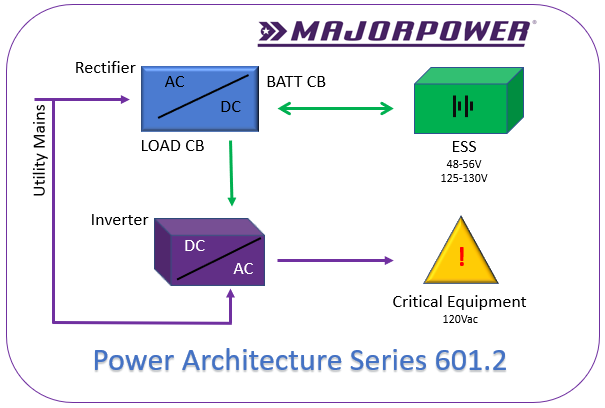
This architecture is a combination of configurations 401.2 and 101.1 as previously discussed in this document. The user’s project, code name Oregon, is a deployment for 2021 and beyond. A typical control and instrumentation network, with multi-node design, is operating on the foundation of this power solution. One rectifier full-chassis system (401.2) is sized to 50-Amp output incorporating features including battery charge, battery Low-Voltage-Disconnect control and individual circuit protective devices for load connection to equipment apparatus. The architecture energy storage system (ESS) is sized to run time design requirements for the application. Each ESS style may react differently depending on factors like load rate, temperature, location size or method of storage. Battery manufacturers publish data for each model characterizing available current draw over time. Critical load equipment operation run time is directly related to the amount of power draw from an ESS (often a battery). Power conversion by the third stage of the architecture, the inverter, (101.1) is connected to source dc from the ESS and secondary ac from a mains circuit for the location.
Project Equipment List 1:
• Rectifier: MTS48/50AT-1U
• ESS/Battery per user selection @ 48vdc operating range
• Inverter: Majorsine1000-48-2U
Rectifier: MTS48/50AT-1U will provide 50 amps of dc in the 48 – 56 Vdc range for both storage charge and inverter operation. One power module (25A rated) is the required dc supply rate to the inverter for maximum capacity operation. The second power module can charge up to 250 AHr of storage, based on a 10% design plan.
Battery 48Vdc(ESS) selection is based on the desired run time of the overall system when a utility source is absent. Typical engineering-design practice for charge current is 10% of the battery AHr storage, that should be supported by the rectifier. By example, 170 AHr * 10% yields a 17 amp availability factor from the rectifier system. Battery selection for a 25A power module should not exceed the 250 AHr capacity rating. Generically, the example 170 AHr size battery can support 6 hours @ 27A to more than 24 hours of operation at lower current draws.
Inverter: Majorsine1000-48-2U will provide 800 watts/1000VA ac to the connected critical equipment. Mainstream equipment is operational with 115-120 Vac. A dc input source of no-less-than 25 amps is required for maximum capacity of the inverter. The actual input dc current is relational to the output ac current utilization by critical equipment plus a small efficiency factor.
Project Equipment List 2:
• Rectifier: MTS130/20AT-1U
• ESS/Battery per user selection @ 130vdc operating range
• Inverter: Majorsine1000-125-2U
Rectifier: MTS130/20AT-1U will provide 20 amps of dc in the 125 – 145 Vdc range for both storage charge and inverter operation. One power module (10A rated) is the required dc supply rate to the inverter for maximum capacity operation. The second power module can charge up to 100 AHr of storage, based on a 10% design plan.
Battery 130Vdc(ESS) selection is based on the desired run time of the overall system when a utility source is absent. Typical engineering-design practice for charge current is 10% of the battery AHr storage, that should be supported by the rectifier. By example, 1100 AHr * 10% yields a 10 amp availability factor from the rectifier system. Battery selection for a 10A power module should not exceed the 100 AHr capacity rating. Generically, the example 100 AHr size battery can support 9 hours @ 11A to more than 24 hours of operation at lower current draws.
Inverter: Majorsine1000-125-2U will provide 800 watts/1000VA ac to the connected critical equipment. Mainstream equipment is operational with 115-120 Vac. A dc input source of no-less-than 10 amps is required for maximum capacity of the inverter. The actual input dc current is relational to the output ac current utilization by critical equipment plus a small efficiency factor.
Cabling and associated interconnections completed on-site shall reference best engineering practice or local standards for the client installation.
DOWNLOADS


