MENU
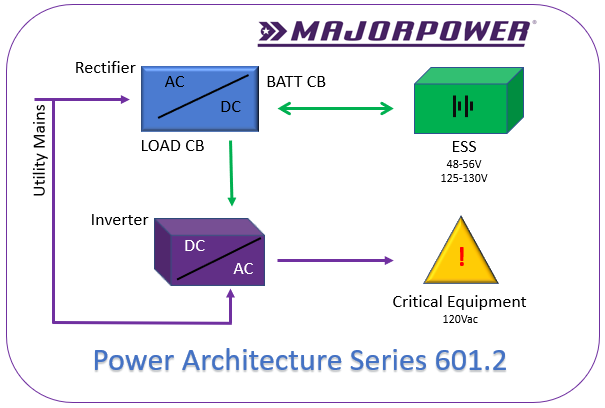
AC-to-AC; ESS/Batteries Sized per Run Time
This power architecture series edition is a combination of configurations 401.2 and 101.1 as previously discussed in this document. The user’s project, named Oregon, is a deployment for 2021 and beyond. A typical control and instrumentation network, with multi-node design, is operating on the foundation of this power solution. One rectifier full-chassis system (401.2) is sized to 50 amp output incorporating features including battery charge, battery Low-Voltage-Disconnect control and individual circuit protective devices for load connection to equipment apparatus. The architecture energy storage system (ESS) is sized to run time design requirements for the application. Each ESS style may react differently depending on factors like load rate, temperature, location size or method of storage. Battery manufacturers publish data for each model characterizing available current draw over time. Critical load equipment operation run time is directly related to the amount of power draw from an ESS (often a battery). Power conversion by the third stage of the architecture, the inverter, (101.1) is connected to source dc from the ESS and secondary ac from a mains circuit for the location.
• Rectifier: MTS48/50AT-1U
• ESS/Battery per user selection @ 48vdc operating range
• Inverter: Majorsine1000-48-2U
Rectifier: MTS48/50AT-1U will provide 50 amps of dc in the 48 – 56 Vdc range for both storage charge and inverter operation. One power module (25A rated) is the required dc supply rate to the inverter for maximum capacity operation. The second power module can charge up to 250 AHr of storage, based on a 10% design plan.
Battery 48Vdc(ESS) selection is based on the desired run time of the overall system when a utility source is absent. Typical engineering-design practice for charge current is 10% of the battery AHr storage, that should be supported by the rectifier. By example, 170 AHr * 10% yields a 17 amp availability factor from the rectifier system. Battery selection for a 25A power module should not exceed the 250 AHr capacity rating. Generically, the example 170 AHr size battery can support 6 hours @ 27A to more than 24 hours of operation at lower current draws.
Inverter: Majorsine1000-48-2U will provide 800 watts/1000VA ac to the connected critical equipment. Mainstream equipment is operational with 115-120 Vac. A dc input source of no-less-than 25 amps is required for maximum capacity of the inverter. The actual input dc current is relational to the output ac current utilization by critical equipment plus a small efficiency factor.
• Rectifier: MTS130/20AT-1U
• ESS/Battery per user selection @ 130vdc operating range
• Inverter: Majorsine1000-125-2U
Rectifier: MTS130/20AT-1U will provide 20 amps of dc in the 125 – 145 Vdc range for both storage charge and inverter operation. One power module (10A rated) is the required dc supply rate to the inverter for maximum capacity operation. The second power module can charge up to 100 AHr of storage, based on a 10% design plan.
Battery 130Vdc(ESS) selection is based on the desired run time of the overall system when a utility source is absent. Typical engineering-design practice for charge current is 10% of the battery AHr storage, that should be supported by the rectifier. By example, 1100 AHr * 10% yields a 10 amp availability factor from the rectifier system. Battery selection for a 10A power module should not exceed the 100 AHr capacity rating. Generically, the example 100 AHr size battery can support 9 hours @ 11A to more than 24 hours of operation at lower current draws.
Inverter: Majorsine1000-125-2U will provide 800 watts/1000VA ac to the connected critical equipment. Mainstream equipment is operational with 115-120 Vac. A dc input source of no-less-than 10 amps is required for maximum capacity of the inverter. The actual input dc current is relational to the output ac current utilization by critical equipment plus a small efficiency factor.
Cabling and associated interconnections completed on-site shall reference best engineering practice or local standards for the client installation.
About the Series
Common Applications
Insights into the most common power architectures using our product line is the focus of the 2021 Insights series. Review this Insider’s Link to applications and creative power architectures deploying power conversion products in the Majortel and Majorsine families. Our Majorpower Applications department answers common questions and shares the collective experience.
@Majortel @MajorpowerCorp


