MENU
Many utility installations already contain Energy Storage Systems (ESS) for maintaining continuous operation during times when a grid supply is not available to the location. For our hybrid systems discussion, consider the ESS being a 130v direct-current (dc) source. A converter power system is used to transform dc at 130V to 48V dc in the shelf system and support the individual protection circuits. The rectifier power system is the same as used in both the single and dual power architecture.
Variation of Sources – Hybrid architectures blend power systems from multiple sources. The most common design will utilize at least one dc and one ac source.
Direct-current (dc) source can provide a scalable run-time for the operation. The dc system profile will likely account for multiple load sources drawing current throughout the design run-time. The profile may be stated in minutes, hours or days. This analysis predicts the amount of storage (sizing) that is desired to support a profile. An ESS can and will vary depending on the goals of each operation or location.
Alternating-current (ac) mains may be derived from the local generation site or a distribution feed from the grid. A simple rectifier power system will transform this ac source into support power for the dc operation, when the utility main source is available.
Converter and Rectifier roles:
A converter is arranged to transform the ESS dc source into a usable dc supply for the load apparatus. This unit is supported by an existing substation asset and likely a 130V dc operation.
A rectifier is arranged to transform the mains ac source into a usable dc supply for the load apparatus. Mains can be either range for nominal 115V or 220V alternating current.
The individual apparatus circuits, labeled A/B, will not differentiate the origin of a dc supply connection. Each input will be appropriately designed for sustained current support at the appropriate operational voltage. Individual protection devices can be integrated into the power system, either converter or rectifier, then connected to the apparatus input.
Picture rectifier power system “MTS-green” protective devices connected to the A input of both loads utilizing individual circuits, then deploy converter power system “MTD-gold” with devices connected to the B input of both loads.
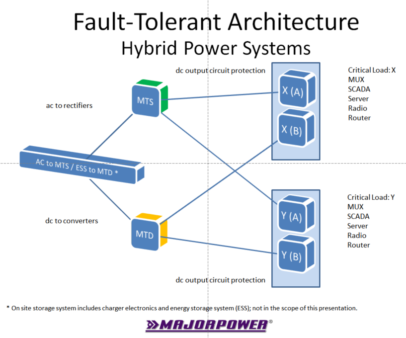
The four connections facilitate isolated and multiple paths for dc power support. The A/B dc support path is now established one level into two power supply systems. The additional second level of fault-tolerant power protection is created by sourcing “mains” ac through the rectifier and sourcing “energy storage” dc through the existing back-up system.
Note: Not pictured here are the electronics to charge a storage system and suitable mechanism to store energy until needed for on-demand delivery. The choice of ESS charging equipment and storage mechanism or chemistry is beyond the scope of this Insights paper. This back-up system design should contain enough dc capacity for full operation of connected devices, including the converter plus an allocation for charging.
#FaultTolerantPower


