MENU
User Question: What does the converter circuit look like in a drawing and explain how the load equipment connects to one or two power conversion modules using the MTD48/25-130-1U or MTD48/50-130-1U converter system?
Insight’s Answer: The Majortel converter system includes a simple Load 1 and Load 2 breaker distribution. The output is designed to support multiple isolated output circuit configurations.
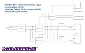
MTD Circuit Line Diagram
Input: A single 130V dc input source will feed the power conversion module(s), dependent on the system deployed. The power conversion modules connect to the converter circuit output busbar, internal to the system.
Output: The output circuit breakers tap the dc busbar to provide independent supplemental protection circuits for load equipment. Each branch circuit device is rated for 50 amps, the system maximum.
Review more details about DC/DC power conversion HERE.


