MENU
Form-C 101 Basic Terms; Normal Relay Settings
A single pole double throw (SPDT) relay is used to actuate the alarm status condition. The relay can switch one circuit (SP) and be placed in 1-of-2 positions (DT). The relay’s “resting state” is the closed position; when no power is applied to the installed system controller. (MTS-Com)
The Majortel (MTS) relay contact surfaces do not contribute any voltage to the circuit. The contact serves as the switch mechanism to open or close a circuit provided by the user’s telemetry system. The relay in the MTS-Com controller is rated for 2A @ 30VDC or 1A @ 125VAC. The operational voltage originates in the user’s monitoring system and the user’s system is typically configurable to recognize open or closed circuits. (NC or NO)
All conditions are normal in the system when the monitored points are within the specified/programmed parameters. Users with approved system access may program the software to define the relay position for normal operation conditions. The relay can be in one of two positions – either CLOSED or OPEN. Therefore, the abbreviations often seen are NC and NO for Normal-Close and Normal-Open, respectively.
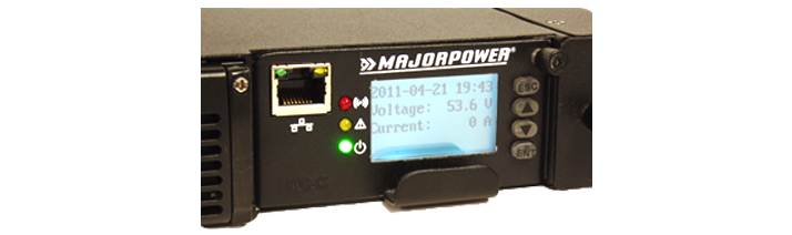
Majortel Controller
The Majortel System controller (MTS-Com) ships in the NC (Normal-Close) relay position as factory default programming.* In the Normal-Close position, the relay will complete a circuit that originates in the user’s monitoring equipment. The function is similar to a light switch position to complete a circuit and illuminate a lamp.
Majortel Systems are designed with two (2) alarm relays initially configured for Major and Minor alarm groups. Users may use the digital controller to map alarms so as to direct each either relay and specify grouping the alarm(s) as Major or Minor.
* The historical telecom standard derived from needing to know if a wire was unintentionally pulled loose from a alarm circuit in the cross-connect or wire-wrap panels during maintenance. This action would “Open” the previously “Closed” circuit.
Accessed using the front-panel system controller screen.

MTS Alarm Connector – back panel:
Test terminal points with continuity meter to verify contact position.
If you have any questions please contact us.


