MENU
Distribution is the key connection point from a power system output to load equipment. Multiple methods can be used based on the requirements of the installation, flexibility for future growth and user preference of life-cycle maintenance. Our designers incorporate many of the most innovative configurations to create a power system that supports a wide array of critical dc supported applications. Take a few moments to browse the information below to see which system can start running the load in your application.
This power system is designed with the integrated GMT load fuse distribution bay, front access visual indication when a fuse is open. The battery circuit breaker, integrated for maintenance convenience, is located on the front, next to the fuse distribution. The circuit breaker separates the battery connection from the core rectifier and load bus when open. The circuit breaker operates independently from the low voltage disconnect (LVD) that is part of the same battery protection circuitry in this system. Viewing a system from the front, the rectifiers and control screen are positioned left and the distribution is right.
Availability in System: MTS48/30FL-1U
Ratings: 10 sockets for loads using standard GMT type fuse; 1 A to 15 A
1 rocker circuit breaker for battery @ 30A; factory installed; non-changeable
The output terminal strip, for secured screw connections, is located on the system backplane. A larger block is provided for the battery ring terminal or single-hole lug landing and arranged in-line with the 10 fuse connections.
Each rectifier connection source should be engineered to provide 10A current at 120VAC. Care should be taken to confirm the electrical service for the application is appropriately sized. Only attach the line cord sets, supplied in the kit, to the properly rated NEMA 5-15R receptacles.
The pre-engineered cable is a NEMA5-15P to IEC320-C13 (right angle) with a length of 6 feet end-to-end. First insert the IEC connector into the back of the system, then use the ty-wraps to secure the cable to the system chassis grill. Lace the cable along the rack to the appropriate NEMA receptacle and AC input source.
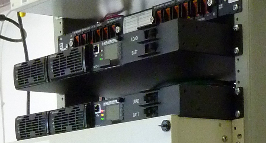
This power system is designed with the integrated load circuit-breaker distribution bay. Users can quickly establish circuit status using the front access visual indicator; a part of the red colored rocker-switch case. These plug-in circuit breakers are field changeable and available in a variety of current ratings.
The battery circuit breaker, integrated for maintenance disconnect convenience, is located on the front next to the load distribution. The circuit breaker separates the battery connection from the main rectifier and load bus when open. The battery circuit breaker operates independently from the low voltage disconnect (LVD) that is part of the same battery protection circuitry in this system.
Availability:
48V power system – MTS48/30BL-1U (four load positions; one battery position)
48V power systems – MTS48/xxxAT-2U (four load positions)
Ratings: plug-in circuit-breaker sized to 5, 10, 15, 20, 30 amp
The output terminal strip, for secured screw connections, is located on the system backplane. Form-C Alarms and Temperature Probe connections are available as well. The ambient temperature probe ships as a standard part with the system kit.
This power system is designed with the integrated load and battery circuit breakers, front access visual indication as a part of the label text on the breaker case. The power block terminal, for secured screw connection, is located on the system backside. This simple bulk configuration provides independent circuit protection and manual control for load and battery outputs. The battery circuit breaker, integrated for maintenance convenience, is located on the front next to the load breaker. The circuit breaker separates the battery connection from the main rectifier and load bus when open. The circuit breaker operates independently from the low voltage disconnect (LVD) that is part of the same battery protection circuitry in this system.
Availability:
48V power system – MTS48/50AT-1U
24V power system – MTS24/50AT-1U
Ratings: Factory installed, non-changeable, load is 50 amp and battery is 50 amp
The output terminal, consisting of secured screw connections, is located on the system backplane. The larger block is provided to support a ring terminal or single-hole lug landing for connection with load bus and battery.
Each rectifier slot is internally connected to a single source entry point, with a screw terminal appropriate to land bare solid copper wire. The typical source AC circuit should be engineered to provide 15A current at 230 VAC of either 50/60 Hz.
This power system is designed with the integrated output circuit-breaker 2-Pole interrupt, front access operation. The two pole power block for secured screw connections is located on the system backside. The circuit breaker separates both the positive and negative circuits between the system output connection and rectifier bus. Due to various applications, the circuit breaker is labeled “load” to indicate any output load in respect to the power system whether a common bus, active loads or battery load combination system.
Available in 130V power systems: MTS130/10AT-1U or MTS130/20AT-1U
Ratings: Factory installed, non-changeable, 2-pole 25 amp
The output terminal, consisting of secured screw connections, is located on the system backplane. The larger block is provided to support a ring terminal or single-hole lug landing for connection with load bus or battery.
Each rectifier slot is internally connected to a single source entry point, with a screw terminal appropriate to land bare solid copper wire. The source AC circuit should be engineered to provide 15A current at 203 VAC of either 50/60 Hz.
This power system is designed with the integrated Load A/B circuit breakers, front access visual indication as a part of the label text on the breaker case. The design incorporates actuator guard barriers to aid in the prevention of unintentional actuator movement.
This simple bulk configuration provides independent circuit protection and manual control for dual load output applications. The circuit breaker separates the main converter module bus and load power block when open. The circuit breakers operate independently from each other and obtain voltage from either power module that is part of the system.
For a full application redundant configuration, interlace two systems with 4 connections spread across two A&B load units.
Availability:
48V converter system – MTD48/25-130-1U & MTD48/50-130-1U
24V converter system – MTD24/25-130-1U & MTD24/50-130-1U
Circuit Breaker Rating: Factory installed, non-changeable, mid-trip 50 amp
Contact us to request Product Information or Ask Questions.