MENU
A. Each new inverter ships with insulated field crimp ring terminals ready for installation.
•1 kVA: Insulated Ring, 12-10AWG, Stud Size – 5/16
•2 kVA: Insulated Ring, 8AWG, Stud Size – 5/16 .
A. Terminal screw size for AC input is M5 x 1.0 or 10-32
AC Input Examples – no >12mm width, Yellow Crimp
3M# MNG1010R
TE# CPGI-B-106-1503-5
Panduit# PN10-10R
STA-KON# RC10-10
AMP 2-324015-1 Fork&Lock
A. Contents of included tool kit:
•Poly zip bag containing twelve M4 screws and two 6-32 screws
•Two large mounting brackets (23”/24” rack mount)
•Two small mounting brackets (19” rack mount)
•One protective cover for AC input
A. The positive and negative input DC posts float relative to earth. The installation dictates if or how a system is referenced to earth.
For Inverters: This means the DC input is floating, therefore suitable applications include +24V cellular/radio sites, -48V telecom applications and floating 130V utility installations.
*The floating reference is only related to DC elements of equipment as it is not related to any AC elements of equipment.
A. The inverters are designed for an input-to-output isolation greater than 1,500 Vdc.
Q. Is there a short period during the specified transfer time (<4ms) that both the inverter and bypass relays are open or is it a make before break transfer?
A. Yes, break-before-make open and the switch time is about 4ms. When the inverter is operated in the off line mode, it will take 6ms to detect the AC I/P failure. Once the AC failure is detected the max transition time is about 10ms.
A. No. The inverters are designed for independent operation. The output of multiple inverters should not be deployed for parallel applications, in an effort to double capacity.
A. We recommend dividing the load connections into smaller bundles. Diversify the application by using smaller bundles attached to multiple inverter output panels. The inverters are designed for independent operation therefore providing multiple source paths to maintain critical application loads.
A. You have a couple of options; Diversify the application by using smaller load bundles and deploy inverters with either INTERLACED or DISTRIBUTED architectures. These models naturally build fault-tolerance and resilience into your application network.
A. No. The inverters are designed for independent operation. The output should not be deployed for grid-tie applications.
A. Theoretical MTBF is greater than 200,000 hours. For detailed specifications per unit, see Model numbers below
Majorsine1000-125-2U= 474,740.06 hours | Majorsine2000-125-2U= 446,373.50 hours
Majorsine1000-48-2U=210,017.93 hours | Majorsine2000-48-2U= 205,817.25 hours
Q. What is the DC IN-RUSH current draw of the Majorsine inverter?
A. The in-rush is < 5 Amps for an inverter with no load.
A. Ratings per model:
Majorsine1000-125-2U = 10A
Majorsine2000-125-2U = 20A
Majorsine1000-48-2U = 25A
Majorsine2000-48-2U = 50A
A. Ratings per model:
• 15 Amps for Majorsine 1000, 120V ac output
• 25 Amps for Majorsine 2000, 120V ac output
• 08 Amp for Majorsine 1000, 230V ac output
• 15 Amp for Majorsine 2000, 230V ac output
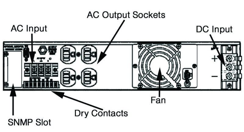
A. The terminal pins are available for either normal-close or normal-open systems. Alarm grouping is fixed and not client configurable per relay. Typical dry-contact rating; terminal can support 5A/250Vac or 5A/30Vdc. This exhibit should answer most questions.
A. The unit will attempt to recover DC mode operation one time before latching itself into AC Bypass mode. Reduce the attached loads and re-commission the inverter to service. Check the status screen for measured percent of utilization.
A. 0.28 Amps for Majorsine1000-125-2U & Majorsine2000-125-2U
0.4 Amps for Majorsine1000-48-2U & Majorsine2000-48-2U
A. Yes; see the instructions in our recent tech-posting. (Link-to-Bypass-Programming)
A. When a FAULT Alarm on the Inverter which reads the following: “AC BYPASS OUT OF FREQUENCY”, power OFF both DC and AC input sources to the inverter. Upon Inverter start-up, applying only the DC source, the front panel will be active for configuration changes ONLY 10 seconds. Use the Data & Status buttons as listed in the operation manual instructions to change and save the frequency of operation. After the inverter completes the start-up sequence, apply the AC input source. No alarm will be present if the configuration matches the external source.
A. Details by Size
|
Majorsine1000 VA units: Watts 800 @ Efficiency 86% Total Requirement 930W Difference (loss) 130 BTU 444 |
Majorsine2000 VA units: Watts 1600 @ Efficiency 86% Total Requirement 1860W Difference (loss) 260 BTU 887 |


