MENU

System Overview Indicators
Numerical values are presented for core system data points of operation. These include Voltage, Current, Power and Temperature. Information displayed is real-time telemetry and graphical on the Dashboard.
NAVIGATION: Select the “System Message” menu and follow “System View” from the left-side panel options.
Available Parameters include:
Output Voltage
Load Current
Output Power
Battery Current
Battery Temperature
Battery SOC
Battery Mode (float; equalize)
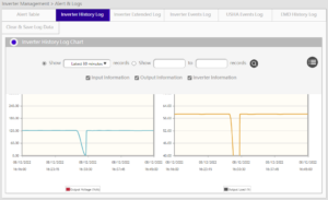
Recent Data Curve Indicator
Users can adjust “recent curve” graphs of current and historical system data.
Data for the graphing display must be curated after the system is energized.
Allow several minutes for the first data set collection.
The first dropdown tab provides access to System or Power Module focused datasets for display on the graph or curve.
Selecting System View presents options in tabs 2 and 3. These options include dropdown choices for:
• Output Voltage
• Load Current
• Output Power
• Ambient Temperature
Make selections to compare the collected data points on the graph.
Selecting Power Module View presents options in tabs 2 and 3. (system dependent modules may be rectifiers or converters) These options include:
• Input Voltage
• Output Voltage
• Output Current
• Current Limit Point
• Inlet Temperature
Power Module Indicators
Read-Only status indicators per power module. The indications are specific to either a rectifier module (RECT) or a converter module (CONV). Information displayed is real-time telemetry.
NAVIGATION: Select the “System Message” menu and follow “Power Module” from the left-side panel options.
Available Parameters include:
Input and Output
Temperatures
Selected internal indicators
Majorsine NMC3 Events Graph
Active Alarm List
Table listing of Real-Time alarm triggers in a system.
NAVIGATION: Drive through the button for full page review of any active alarm.
The Historical Alarm tab is also available to query the alarm data storage.
Selection of alarm type and date will filter results.
System Status Indicators
Conditional values are presented for circuit breaker condition, voltage alarm trigger points and digital input conditions. Information displayed is real-time telemetry.
NAVIGATION: Select the “System Message” menu and follow “System Status” from the left-side panel options.
Available Parameters include:
Load Circuit Breakers
Battery Circuit Breakers
Battery Contactor Position
AC Input
DC Output (High/Low)
Battery Charge Current
Temperature (High/Low)
Digital Input Indicators
[[ Back To Quick Set Home ]]


